A Low-Cost Dome to Track Drones and DARTS
Posted on 02 Jul 2026; 10:00 AM IST. Last Updated 04 Jul 2026; 11:30 PM IST.Summary: This article describes a low-cost dome, which can be used to track drones and DARTS.
Drones and DARTS (Direct Attack Rocket Technology), have become a menace to industrial estates, and the rapid advancements
taking place in this area, may make the world less safe.
The biggest problem with Drones and DARTS is that they are extremely cheap, and rely on "drifting" rather than "flying". All the
defence mechanisms built in the last century, assume that the incoming projectile, makes some kind of a volley. Needless to say,
the drifting drones and DARTS are difficult to track, and neutralize.
The rest of the article describes how a low-cost dome can be built, for tracking Drones and DARTS from well-known technologies.
Background Technologies:
MANETS (Mobile Adhoc Networks) are very well known in electronics and computing industries, and are extensively studied in Mobile
Computing.
Typically, MANETS use small cheap sensors, to capture and transmit information, in remote areas. The real power of MANETS comes
from the fact that the underlying network is adhoc, and they do not need a big infrastructure.
Long Enduring Drones (LED-drones) can stay afloat for 8 to 10 hours or longer, and can carry a reasonable sized payload, like a
50 km RF Transmitter. The LED-drones stay at a fixed height, which is typically set at 5km or about 16,000 ft.
Design of the low-cost dome:
The design of the low-cost dome, to track drones and DARTS, employs LED-drones to hold the payload. The LED-drones encircle the
perimeter of a resource, like an industrial estate, that needs to be protected, as shown in the figure below.
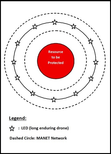
As can be seen from the diagram, there are three concentric circles around the perimeter of the resource to be protected.
The dashed circles represent the MANET (sensor) network, and the Star circle represents the LED-drone network.
The resource to be protected is assumed to be contained in a circle of 10km diameter. The Star circle is about 20 km range from the
outer edge of the resource circle. The dashed circles or MANET networks are about a distance of 1 km from the Star circle.
From the geometry of the circles, it is easy to observe that each LED-drone can reach another LED-drone on the opposite side of the
circle, and the distance between them is 50 km. This distance is nothing but the maximum distance the RF Transmitter held by the
LED-drone as payload, could transmit the RF signal, without major loss.
For each LED-drone, there are two sets of receivers –
-
The first set of receivers are the LED-drones on the Star circle, which are on the same horizontal plane, but opposite to
the current LED-drone.
We could imagine LED-drones of the Star Circle, as numbers 1 to 12 of a clock. This allows us to conclude that 12 is directly opposite to 6; and 5 and 7, which are neighbours of 6, are at an angle of 15 degrees from 12. The angle between 7, 12, and 5 is 30 degrees.
If a single RF Transmitter sweeps 30 degrees (beamwidth), then the 12 RF Transmitters in the payloads of the 12 Led-drones sweep the full 360 degrees.
-
The second set of receivers are the sensors of the MANET network, which are close to the Star circle horizontally, but are
vertically below it. The RF Transmitter has to transmit to MANET network, at a very steep angle of above 60-degrees.
To mitigate this issue, the LED-drone could carry two RF Transmitters, one for communicating with other LED-drones, and another for communicating with MANETS.
It may be noted that a LED-drone and the MANET sensors form a simple right angled triangle, with 5km as height, and 1km as base.
The base angle of the triangle is:
[sin inv(5 / sqrt(26))] = 78.69 degrees;
The angle subtended by LED-drone to MANETS is:
90 - 78.69 = 11.31 degrees;
Under this arrangement, the two MANET networks fall under 30 degrees sweep (beamwidth) of the RF transmitter.
The MANET networks connect to controllers (not shown in the diagram), which detect threats. The controllers in turn connect to a Command center (not shown in the diagram), which evaluates the threat, and the future course of action.
The two sets of receivers create two layers of RF signal firewall.
Operation of the low-cost dome:
When a drifting threat such as a drone or DART passes through the RF-firewall, created by the LED-drones and the MANET sensors, then the controller connected to the MANET network, would detect the threat. In this case, the controllers of the two MANET sensor networks, would detect a breach.
If a threat descends directly from above 16,000 ft or 5km, then the RF-firewall created by the LED-drones would be breached, and the LED-drones, could detect the threat. In this case, ALL the RF Transmitters, could receive a signal reflected by the threat.
When a threat is detected it is reported to a Command center, which analyses the threat, and instructs "hunter drones" on stand-by (at an unspecified height), to analyse the threat.
The hunter drones could collect snaps of the threat, and relay the information to Command center, and wait for further instructions.
Technical Details:
In this section a few important details of the scheme are detailed.
-
The RF Transmitter described in the article is actually a RF Transceiver.
-
The radius of the Star circle is 25 km; and its diameter is 50km.
The circumference of the star circle =
2 x (22/7) x 25 = 157.08 km.
Since there are 12 LED-drones around the circle; Each Led-drone must cover a distance of: 157.08 / 12 = 13.1 km.
It is assumed that the horizontal RF Transmitter (or Transceiver) could transmit a signal to 50km, at 30 degree beamwidth angle.
beamwidth = 2 × Distance × tan (θ / 2)
= 2 x 50 x tan (30/2) = 26.79 km
The beamwidth adequately covers the required portion of the circumference. Strictly speaking, the beamwidth covers twice the circumference, when all 12 LED-drones are taken into consideration. The inscribed angle theorem explains this phenomenon.
-
When a threat descends directly from above, it is detected by all 12 RF Transmitters,
which could determine the RF signal of the threat, as well as its position, including
a fragment of the path of descent, by triangulation.
-
When a threat drifts from below the LED-drone height (5 km), then the vertical
RF Transmitter could detect the threat, but it cannot identify the exact position
of the threat. The position could only be identified by the sensors of the MANET network.
-
If the sensors are laid out along the dashed circles, then we could determine,
only the entry and exit points of the threat. It may be noted that the vertical
RF Transmitter could cover the entire width of 2km range between the dashed circles.
If the sensors of the MANET network, are laid out densely in this region,
we could get a better foot print or path of the threat.
-
The MANET network could be broken into sections, and each section could be connected
to an individual controller. The Command centers may also be duplicated to improve efficiency.
-
The vertical RF transmitter, should also cover a distance of 13 km, along the dashed circles,
like the horizontal RF Transmitter described in #2 above.
To accomplish this the beamwidth angle must be set at 120 degrees.
beamwidth = 2 × Distance × tan (θ / 2)
= 2 x 5 x tan (120 / 2)
= 17.32 km.
This beamwidth adequately covers the required distance of 13km.
If the RF Transmitter could send a signal across 50 km at 30 degrees, then at 120 degrees the signal could be transmitted without loss, to a much shorter distance. The range factor for 120 degrees is computed as shown below.
G-120 / G-30 = square(30 / 120)
= 1 / 16;
R-120 / R-30 = sqrt(G-120 / G-30)
= sqrt(1 / 16) = 1 / 4;
The range of the transmitter would diminish from 50km to -
50 x 1 / 4 = 12.5 km;
This is range exceeds the height of the LED-drone (5 km).
The hardware was described very abstractly, and the low level hardware design, is beyond the scope of this article.
The dome must ensure that there are no airports nearby, and the LED-drones must send pre-warning signal, for low flying aircraft and helicopters.
The RF signals could interfere with other communications; this needs to be evaluated independently, on case-by-case basis.
The design allows for additional layers of defence at 100 km, or 150 km, from the resource, using the same architecture.
A multi-layered defence could be more pragmatic, and the LED-drones of each layer may be placed at different heights, for maximum protection.